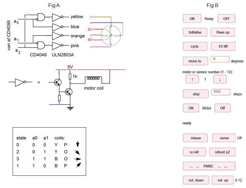
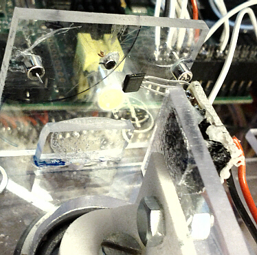
I've been too busy to work on Poepie2 (P2) for somewhat more than two years. But now I am at it again. After I made a few "improvements" Poepies behaviour became erratic, due to mistakes in addressing the motors. To help myself in debugging I made the drawing below that depicts the inputs to a single motor. The driver, ULN2803A is addressed by three address bits: a0, a1, a2.
The outputs of the AND gates input to 4 of the 8 Darlington driver stages of the ULN2803A as shown in figure A below.
To prevent the possibility that motors remain in a state other
than state 0 for long times and thus drawing current for nothing, the routine Step() has been split into two routines HStep() and VStep(). HStep as not changed much, but VStep now only makes complete motor cycles, i.e. it goes through the 4 states, starting at 0 and ending at 0, with adress a2 set at the end to 0 too. The routine Lift2Paws() has been changed as well. The modified file stepper.c is available.
The html page to command P2 has been updated as well (Fig. B). For most commands, the buttons do not respond anymore (and don't emit a click sound) until the ongoing action is terminated. It has now a "panic" button to shut down the driver cards when something goes wrong during debugging.
Poepie2
A never ending project, aiming to make an artificial cat controlled by the Raspberry Pi.
contents
0 introduction1 hello.c
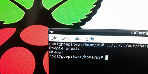
2 leds
3 3.5" diskette motor driver
4 wifi, command the RPi via internet
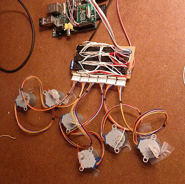
5 a driver for 6 stepper motors
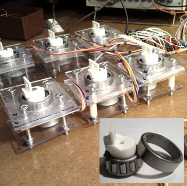
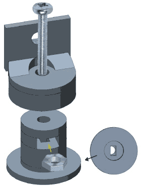
6 mounting the 6 horizontally turning stepper motors
7 a relay and a battery added
8 test the motors via the web
9 Poepie2 miaows
10 Hall sensor feedback
11 new printed legs
12 the first steps
12 a few modifications to stepper.c
introduction
I had my Raspberry Pi (RPi) hooked up on my television set, keyboard and mouse for some time. That worked well but took a lot of space on my desk. Moreover, the video interface consumes apparently a lot of processor time. To have access to the internet I've bought a wifi usb key. For the project wifi, command the RPi via internet I've given the RPi a fixed IP address and installed the apache web server on it that at the same time sets up SSH. SSH can also be configured following the instructions on this page. Now the RPi can be controlled via telnet on another computer, in my case using PuTTY on PC or ConnectBot on my android pad. I exchange files using Filezilla configured to SFTP (secure FTP). Works perfectly!
The Rpi will be the brain of what will hopefully become a six legged robot cat (P2).
The articles in this blog are in reverse chronological order. Go to the first article.
Poepies first steps are somewhat hesitant and the routines that make it walk need obviously some improvement. The stepper.c, step.php and index.html files have been updated. The sound.php file has become obsolete: I've found that it is impossible to call mpg123.exe on the RPi from a php script. Many people have encountered the same problem, but no one has found the solution to this problem. Mpg123 is now called from the resident c program (stepper.c).
The first steps are shown on youtube and the control layout for the smartphone is shown on the right:
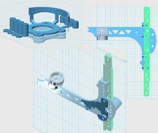
When I first tried to get Poepie up and walking it went into the splits. This because the tolerance of the mechanical parts that I sawed by hand was to high (0.5-1 mm). To have parts that join with much higher precision I decided to have them printed. I've given up on the Sculpteo service because they changed their policy making printing far too expensive: You have to order each part separately for a minimum price per part of over 6€, even if the part is only 3x3 mm. In stead I turned to Shapeways in the US that lets you pack as many objects you like in a volume. You pay a weighed sum of volume occupied in the printer and final volume of the objects, which is much more reasonable than the Sculpteo proposal. The autodesk 123D file can be found here.
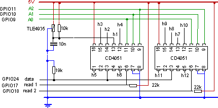
The RPi does not know the position of the arms of the cat upon start-up. Several solutions exist to remedy this potential problem, amongst which proximity sensors based on the Hall effect. I've chosen the TLE4935 sensor, available in France from Gotronic. Since Poepie2 uses 12 motors, 12 sensors are required. Just as for the motors, I've chosen for serial to parallel conversion to save GPIO lines. This time the RPi has to input data in stead of outputting it as in the previous entries. I've chosen the CD4051 8-channel analog multiplexer/demultiplexer to do the job. In the schematics below, only the wiring for a single Hall sensor is shown (consisting of TLE40935, the 10k resistor and the 10nF condensor) that goes to pin 13 labeled 'h1'. The same circuit has to be repeated for the other 11 inputs h2 through h11. The CD4051 and the capacitors reside on the main board, while the TLE and the 10k resistor are soldered onto a tiny board that is then glued onto an arm of the cat (see photo below). Only two new GPIO lines are needed, i.e. GPIO17 & 18. The same data line (GPIO24) is used for the motors. The 19K resistor from data line to ground is important as it divides the 5V input such that the RPI sees only 3.3V. RPis may be damaged if exposed to more than 3.3V on the GPIO lines. Three small magnets are glued onto the perspex window facing the three-legged TLE40935. The middle magnet 1mmx2mm has the opposite magnetisation as the two magnets 3mm x 3mm at the extremities.
Now, after startup of the RPi, the motors can be positioned. The C routine shown below makes the arm swing in increasingly larger sweeps until it has figured out the position of the central magnet. In this particular case, the center magnet causes the TLE-signal to be low, while the magnets at the extremities cause it to be high.
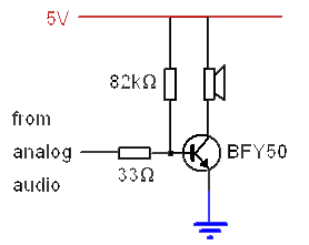
I have amplified one of the stereo channels from the analog audio output using the NPN BFY50 transistor such that it can drive a 8 Ohm miniture loudspeaker. In the figure below, the bias base current is chosen such that the base potential barely exceeds the junction potential (~0.7 V). The value of the resistor (82 kOhm in this case) is critical and depends probably on each individual RPi. If the resistor is chosen too high, no sound comes out. If it's too low, too much current is drawn (approximately 100 times the base current) and the transistor heats up for nothing.
The result can be found on youtube:
In order to to be able to play sounds, in particular mp3 records, sound on the Rpi needs to be enabled and then a mp3 player (mgp123) installed. I followed the instructions by J. Pinilla and H. Becerra. In the following I have removed the parts that did not work correctly.
Use SuperUser (After every reboot) or use sudo before any command
sudo su
Install Firmware Updater
apt-get install ca-certificates git-core binutils
wget https://raw.github.com/Hexxeh/rpi-update/master/rpi-update
cp rpi-update /usr/local/bin/rpi-update
chmod +x /usr/local/bin/rpi-update
Update Firmware
sudo rpi-update
Uncomment "hdmi_drive=2" on config.txt
nano /boot/config.txt
Install ALSA, MPlayer and PulseAudio
apt-get install mplayer mplayer-gui alsa-base alsa-utils pulseaudio mpg123
Add audio module to kernel
modprobe snd_bcm2835
echo 'snd_bcm2835' >> /etc/modules
Configure ALSA driver for n Analog=1 HDMI=2 (Auto=0 Not recommended)
amixer cset numid=3 n
Replace asound.conf (An empty file in my case) with:
pcm.!default {
type hw
card 0
}
ctl.!default {
type hw
card 0
}
nano /etc/asound.conf
Reboot Raspberry Pi
reboot
Test audio with ALSA Test analog output
amixer cset numid=3 1
speaker-test -t sine -f 600
Download mp3 file miauw.mp3
wget http://bram.org/RPi/miauw.mp3
Play MP3 file
mpg123 miauw.mp3
The index.html file contains:
The step.php file contains:
I've put the following text in the script file "/etc/init.d/p2init":
The c code to initialise the 12 motors is:
The c code to (test)drive each of the 12 motors and to switch the relay is:
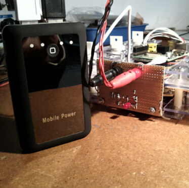
I've bought a set of rechargable batteries, a RoHS 6600mAh 5V dual power bank (see photo below). One battery delivers 1A to which I connect the Raspberry Pi, the other battery delivers 2A and is used to power the drivers and the motors. This should be enough for 2-3 h autonomy.
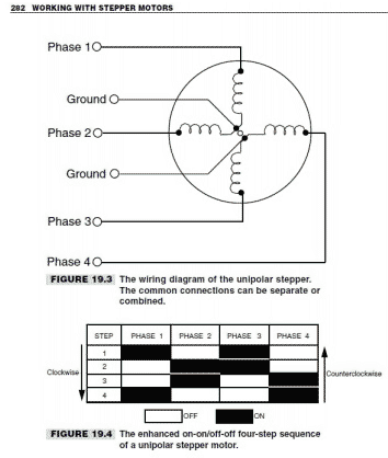
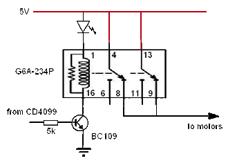
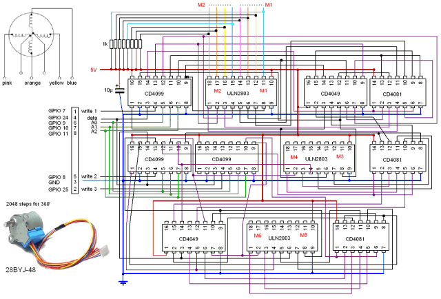
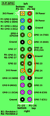
As can be seen in the figure labelled 19.4, phase 1 is always the inverse of phase 2, i.e. when one is ON the other is OFF. The same for phases 3 & 4. Hence the signal to drive phases 2 and 4 can be obtained by inverting phase 1 and 3. I've chosen the CD4049 hex inverter chip to do this. With the CD4099 8-bit adressable latch, simple serial to parallel conversion can be carried out. 8 connection lines can thus be reduced to 3. In the circuit diagram below, the current for the motors is delivered by the ULN2803 octal darlington transistor array. The CD4081 chips have been included to make it possible to switch the motors off and thus to save energy. As a result 6 motors need latch adresses for phases 1 and 3 and on/off, which gives 3*6=18 adresses. A single CD4099 chip provides only 8 address and therefore 3 CD4099s are required. The data line and the A0,A1 and A2 addres lines are common to the three chips. The write 1, 2 and 3 lines determine which CD4099 is concerned. I've chosen the GPIO lines 7,8,9,10,11,24,25 to do the job. With the ground connection this makes use of 8 GPIO lines. 2 extra lines will be necessary to address six more motors on a second card. Note that all ULN2803 outputs have 1kOhm pull-up resistors connected to 5V. The wiring of these outputs is shown for only 1 ULN2803. The other 2 chips are connected identically. The 10µF condensor has been included to remove glitches on the 5V power line.
The c code to drive the 6 motors is shown below:
The web page, "p2-leds.php, is in HTML5, such that it is smartphone compatible. It makes use of the jquery javascript library. When a led button is pressed the web page calls another php script using the GET method of jquiry: $.get("../scripts/steer.php?leds="+state").
Next, steer.php writes the new led states in the file "led-state.txt" for the C program to read:
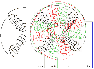
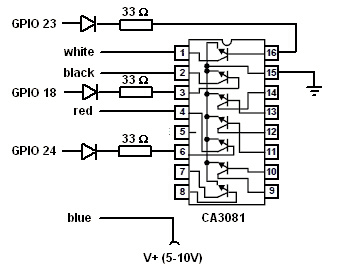
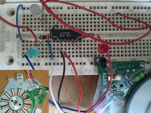
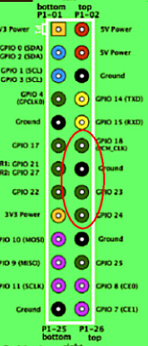
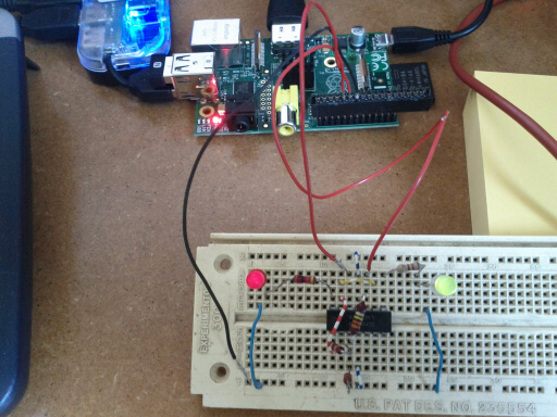
I found useful information on stepper motors at the robotics universe site, even though the 3.5" diskette drive stepper motor (see inset in the photo below) was not described. It took me some time to figure out how the wiring of this apparently tri-phasic motor works. The motor has 4 wires, which were coloured black, blue, red and white. The black wire connects to 4 coils in series, the white to 4 other coils and the red wire goes to the third quartet of coils. The blue is common to all three quartets of coils. I found a CA3081 chip in my drawer that contains 7 NPN transistors with common emitter. These transistors provide just enough current to make the motor spin, but not more than that. For real applications other transistors are required or a second power amplification step should be added. Because of the common emitter, which needs to be connected to ground, the blue line goes V+ (5V...10V). The black, white and red wires connect to the transistor collectors, pins 2,1 and 4 respectively. I've chosen to drive the transistor bases by the GPIO outputs 18,23 and 24 via light emitting diodes for debugging. The c program is a modified version of the one in the previous 'leds' article. Each of the three quartets of coils gets activated in sequence.
To compile: gcc -o hello hello.c